1993 Toyota Corolla (US-Spec): technical information
Also see our drivetrain section featuring transmissions, axles, and driveshafts!
Brakes
- The front brake cylinder was changed to the slide pin construction used on the Camry.
- ABS (Anti-lock Brake System) was an option on all models without theft deterrent systems. It was basically the same in construction and operation as that for the '92 Camry and Celica except for the construction of the ABS actuator.
- A tandem type brake booster was used with the ABS option, similar to Camry and Celica.
|
||||||||||||||||||||||||||||||||||||||||||||||||||||||||||||||||
ABS (Anti-Lock Brake System)
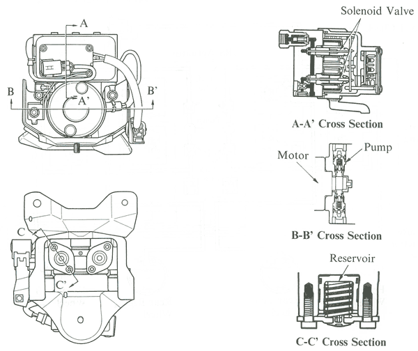
The ABS controlled the brake fluid pressure applied to the wheel cylinders. That prevented the wheels from locking up during a panic stop. Aside from the 2-position solenoid valve adopted in the ABS actuator, the basic construction and operation of this system are the same as those of the '92 Camry and Celica.
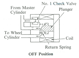
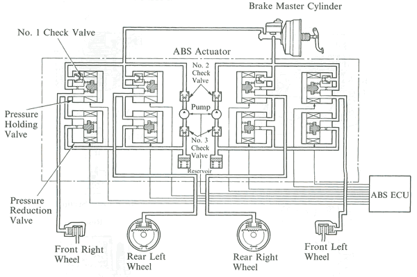
The ABS actuator with four 3-position solenoid valves used in the '92 Camry and Celica was replaced by a new type actuator having eight 2 position solenoid valves in the '93 Corolla. The new ABS actuator was composed of two functionally divided components, namely the control unit and the pressure reduction unit, as in the previous 3 position solenoid valve type actuator. These two units had the same function but the control unit had different solenoid valves as shown below:
The pressure holding valve controlled (opened and closed) the circuit between the brake master cylinder and the wheel cylinder. The brake fluid pressure from the brake master cylinder and the wheel cylinder was turned on and off accordingly.
The pressure reduction valve controlled (opened and closed) the circuit between the wheel cylinder and the reservoir. The brake fluid pressure from the wheel cylinder to the reservoir was turned on and off accordingly.
Front Suspension
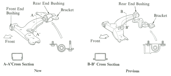
A MacPherson strut type front suspension with an L-shaped lower arm as a strut bar was used, with changes to increase cornering performance and directional stability:
- The lower arm length and shape were changed along with the bushings
- The 7A-FE engine models had ball-joint type stabilizer link. It was the same in basic construction and operation as that of the '91 Corolla models with the 4A-GE engine.
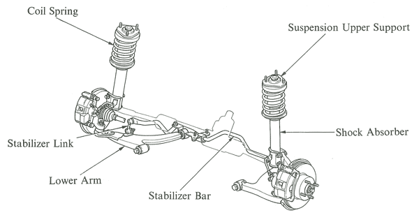
The cross section structure of the lower arm was changed to reduce the unsprung weight. The rear side bushing was now integrated with the bracket, but in the previous model it used to be separate from the bracket. At the same time, the bushing shape was changed to provide more precise steering response when driving straight and during cornering, as well as to improve trace characteristics. A front end bushing with steel inter-ring was used. Its structure was the same as in the previous model.
Rear Suspension
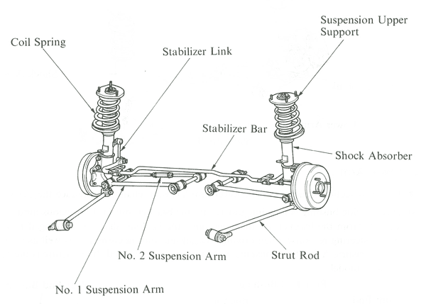
Dual link MacPherson strut type suspension was used at the rear as with previous models. But the following changes were made to increase steering stability and suspension rigidity:
- No. 1 and No 2 suspension arms were increased in both their span and length, as in the '92 Camry.
- The central diameter of the coil spring was increased, as in the '92 Camry, to increase the amount of offset of the shock absorber.
- The bushing of No. 2 suspension arm had an inter-ring as in that of the '91 Corolla rarrying the 4A-GE engine.
- All models adopted the same front suspension used in the 7A-FE models, which were equipped with a ball-joint type stabilizer link.
Steering
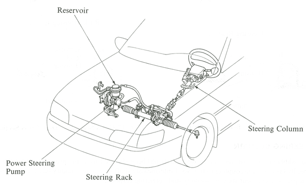
The rack and pinion steering gear was kept, but the tilt mechanism of the steering column was changed to that of the '92 Camry to further improve the ease of operation. The support of the steering rack housing and the rubber coupling of the intermediate shaft were changed for better feel.
Specifications
| Model | 1993-97 | 1992 | ||
|---|---|---|---|---|
| Steering Type | Manual | Power | Manual | Power |
| Gear Ratio (Overall) | 22.7 | 18.5 | 24.1 | 18.7*, 19.1** |
| Nos. of Turn Lock to Lock | 4.09 | 3.35 | 4.28 | 3.27*, 3.35** |
| Rack Stroke mm (in.) | 142 (5.59) | 131 (5.16) | 140 (5.51) | 131 (5.16) |
* KOYO SEIKO Product / ** TOYOTA Product
Steering Column
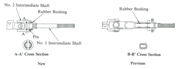
The rubber coupling on the intermediate shaft was changed from the press fit type to the pin type. By fastening the coupling to the No. 1 intermediate shaft with a pin, rigidity was increased. That provided excellent steering stability and cornering response. The pin type couplings also reduces noise transmitted from the power steering system to the steering column.
Body
The body was made more rigid by increasing the rigidity of each pillar joint, optimum reinforcement of the spring support section of the front and rear suspension, increased use of high strength sheet steel, and refinement of the shape and construction of each part. Light weight and highly rigid high strength sheet steel was used for the engine hood, door panels and members.
Optimizing the construction of joints between panels and the location of reinforcements, utilizing continuity of underbody members, increasing the size of the member cross-section and reinforcing the suspension installation parts also increased rigidity. The side member panel was unified, and on doors, reinforcement was added to each joint and a side impact protection beam was used to provide high rigidity.
Use of anti-corrosion sheet was increased and wax and scaler and PVC (Polyvinyl Chloride) coating was applied to the more rust-susceptible parts such as the edges of the door and engine hood, and the underbody to improve rust resistant performance.
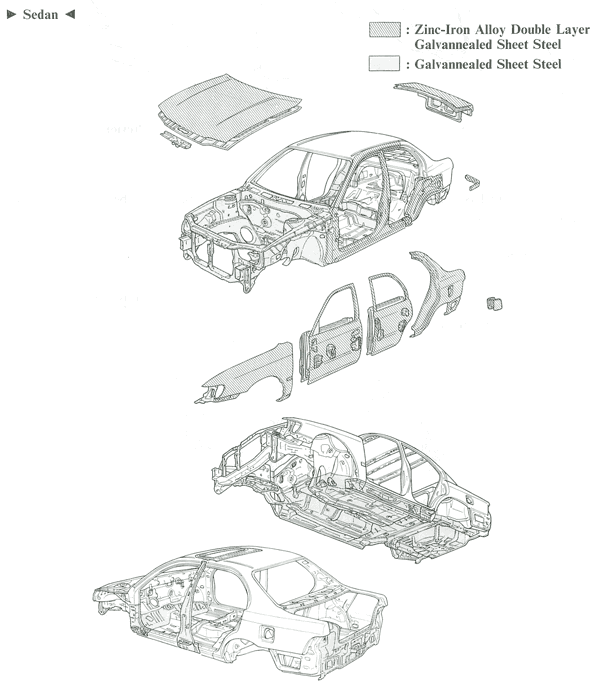
Two types of anti-corrosion sheet steel were used: galvannealed steel and zinc iron alloy double layer galvannealed sheet steel. Galvannealed steel was used for many inner panels, engine compartment, etc. Zinc-iron alloy double layer galvannealed sheet steel was used for major outer panels such as the engine hood, doors and luggage compartment door.
 |
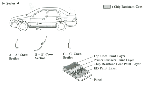 |
Wax or sealer was applied to the hemmed portions of the engine hood, door panels and luggage compartment door to improve rust-resistance. The underbody was coated with PCV to a thickness of 0.5 mm (0.019in.) over the entire area and 1.0 mm (0.039 in.) at panel joints to increase the vehicle's rust-resistance. A chip resistant coat was applied to rocker panels and front and rear wheel arches to protect them from flying stones.
The noise and vibration level was minimized by using vibration damping sheet in more areas, effective arrangement of asphalt sheets, use of a multi-layer composite structure and increased use of foamed polyurethane.
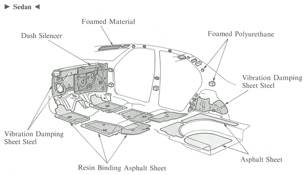
A vibration damping sheet steel consisted of an asphalt sheet sandwiched between two sheet steels in a unitary construction for effective damping of panel vibration and noise.
In all vehicles, the passenger compartment side of the dash panel was fitted with a silencer consisting of a vinyl chloride outer surface with a backing of felt layers to cut out engine noise.
Resin binding asphalt sheets used under the carpet had 3-layered structure. Asphalt sheet was added to sheet steel, then a heat hardened resin layer was added on top for binding. Vibration energy caused the asphalt sheet to stretch, and was thus absorbed. The addition of the resin layer distorted the asphalt sheet. This distortion caused even more vibration energy to be absorbed.
Aerodynamics
To improve aerodynamic performance, flush mounting was used wherever possible, and the following measures were taken:
| No. | Details | Model | |
|---|---|---|---|
| Sedan | Wagon | ||
| 1 | The low, streamlined engine hood leading edge had low air resistance and front lift. | x | x |
| 2 | The wheel arch design of the fender was changed. The bumper and fender were flush-mounted and well rounded so that the front side corners provide a smooth air flow. | x | x |
| 3 | Flush front pillars and cabin provided smoother wind flow. | x | x |
| 4 | Aerodynamic outside rear view mirrors. | x | x |
| 5 | A rear window and rear pillars that increased aerodynamic performance without sacrificing roominess. | x | - |
| 6 | The high-deck rear compartment door had an aerodynamically advanced rear end. | x | - |
| 7 | The tapered rear fender provided smooth wind flow to the back of the vehicle. | x | x |
| 8 | The flat wheel cap had excellent aerodynamic performance. | x | - |
| 9 | The under shape of the front bumper provided good aerodynamic performance and ingine cooling. | x | x |
| 10 | The front fender liner with good aerodynamics and brake cooling performance was smoothly connected to the bumper. | x | x |
| 11 | The flat bottom of the spare tire case smoothly connects to the rear bumper. | x | x |
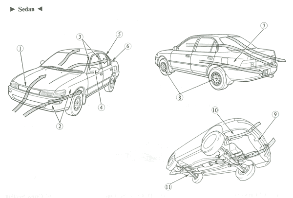
To increase aerodynamic performance and reduce air flow resistance, each part was flush-mounted; minimizing the step and gap at the engine hood/body and trunk lid/body areas enhanced the appearance and reduced noise and vibration.
The front door window regulator was changed from the X-arm type to the cable type to provide smoother operation and reduce weight. The rear door still had the singal arm type window regulator.
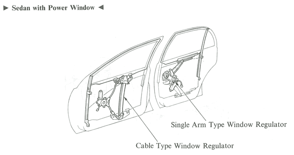
The front door glass was fitted to the carrier plate, which moves up and down the main guide. The window regulator cables wound around the drum in the motor, with the cable ended fixed at the top and bottom of the drum. The carrier plate was attached to the cables and moved up and down in accordance with the movement of the cables.
When the power window motor or window regulator handle was rotated to the up side, the cable at the top of the drum wound in and the cable at the lower side wound out from the drum an equal extent, causing the carrier plate to rise. When the motor or regulator handle was rotated to the down side, the operation was reversed and the carrier plate was lowered.
Body Electrical
Daytime running lights and an automatic light shutoff system were added; DRLs were only used in Canada.
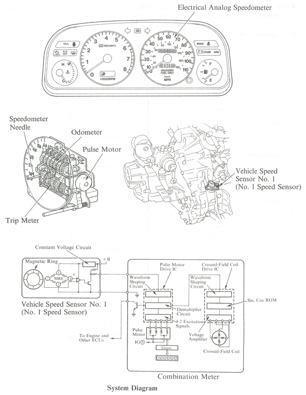
The speedometer of this Corolla was cableless, electrical analog type, which was already in the Previa and Camry. The odometer was changed to the pulse motor driven type. The basic construction and operation of the speedometer and odometer were the same as in the Previa.
Air Conditioning / Heat
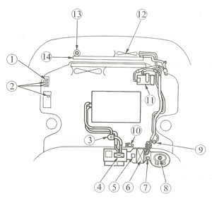
The Corolla had a full air mix type heater and ventilator. The air conditioning was standard equipment on LE grade model for the U.S.A. and optional on all other models for the U.S.A. and models for Canada. The adoption of a three-passage flow type condenser, larger electric fan, and drawn-cup type evaporator in the air conditioning increased its cooling efficiency. The fulcrum of the blower switch was moved further in. This made switch operation smoother, as less effort was required to press the lever.
| Model | Performance Specifications | |
|---|---|---|
| Heater | Heat Output (MJ/h [kcal/h]) | 15.07 [3600], 17.58 [4200]* |
| Air Flow Volume (m3/h) | 320.330* in 1993; 300 in 1992 | |
| Power Consumption (W) | 170 in 1993; 160 in 1992 | |
| Air Conditioning | Heat Output (MJ/h [kcal/h]) | 17.58 [4200] in 1993; 15.07 in 1992 |
| Air Flow Volume (m3/h) | 475 | |
| Power Consumption (W) | 200 | |
 |
|
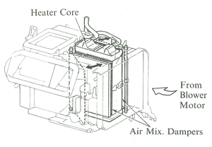
As in the previous models, the three-flow level type heater unit had a pair of air mix control dampers. The heater core was at the center of the heater unit to minimize ventilation resistance.
The evaporator was the same type of drawn cup type evaporator, with high heat exchange efficiency, which was used in the Corolla and other models in the past. A 10PA15 type compressor was used, with the same basic construction and operation were the same as in the previous Corolla. The three-passage flow type condenser had three passages for the refrigerant, resulting in a greater heat exchanging capability. The condenser fan was the blower type. In combination with the radiator fan, the condenser fan speed was controlled in three steps (stop, low and high) according to refrigerant pressure and the engine coolant temperature. The basic construction and operation were the same as in the previous Corolla.
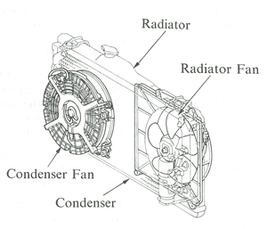
The air conditioning amplifier was mounted on top of the cooling unit. The basic functions of this amplifier were the same as in the previous Corolla.
All functions were the same as in the previous 4A-FE engined Corolla models. When the blower switch and the A/C switch were turned on together, the magnetic clutch relay turned on and activated the compressor. When one of the following conditions was met while the compressor was turned on, the magnetic clutch relay was turned off and stoped the compressor.
- The refrigerator pressure was too low or too high and the low or high pressure switch of the dual pressure switch was turned off.
- The air temperature immediately after passage through the evaporator was detected by the thermistor to be below 30°C (37.4°F).
- "Air conditioning cut" was requested by the ECM* (engine ECU).
When the compressor was operating or was stopped due to a request from the ECM* (engine ECU), an idle-up signal was sent to the ECM (engine ECU).
Airbags
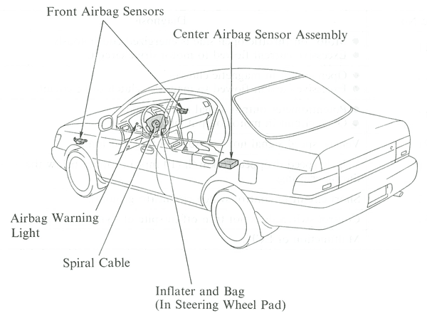
The SRS (Supplemental Restraint System) airbag, together with the seat belt, was designed to help protect the driver. In a collision, the airbag sensors detect the shock and if the front-to-rear shock was greater than a specified value, the airbag stored in the steering wheel pad was inflated instantaneously to help reduce the shock to the driver. The airbag system was controlled by the center airbag sensor assembly. It had a self-diagnosis function. When it detected a system malfunction, it lighted up the airbag warning light on the combination meter to alert the driver. The system components, construction and operation were the same as in the Celica. Major function parts of the airbag are shown below:
Cruise control
This Corolla used the same motor type actuator as that used in the GT-S and All-Trac/4WD grades of the Celica. The basic construction and system operation were the same as in the Celica, but a tap-down/tap-up control was added, and diagnostic codes were modified as shown below:
| Code No. | Diagnosis |
|---|---|
| 11 |
|
| 12 |
|
| 13 |
|
| 21 | Vehicle speed signal not sent for 140 msec. or longer. |
| 23 | Vehicle speed dropped 16 km/h (10 mph) or more below the set speed during cruising. |
| 32 | Short circuit in control switch circuit (to ground). |
| 34 | Control switch did not turn off in spite of switching. |
| 41 | Malfunction of ECU. |
To read the codes, a mechanic would turn the key on, connect terminals Te and E1 of the check connector in the engine compartment, and watch the power indicator light to count the blinks.
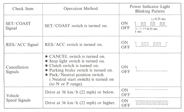
The input signal check mode was set by operating the ignition key, control switch and main switch in the order given below:
- Turn the ignition key to ON position
- Push the control switch to SET/COAST or RESUME/ACCEL and keep it there while turning the main switch ON. Then hold SET/COAST or RESUME/ACCEL position 3 seconds.
- Check that the power indicator light blinks twice.
Input Signal Check Function
Major Technical Specifications Table
| Item | U.S.A. | ||||
|---|---|---|---|---|---|
| Body Type | 4-Door Sedan | ||||
| Vehicle Grade | STD | ||||
| Model Code | No. | AE101L-AEMDKA | AE101L-AEHDKA | ||
| Major Dimentions and Vehicle Weights |
Overall | Length mm (in.) | 1 | 4370 (172.0) | --- |
| Width mm (in.) | 2 | 1685 (66.3) | --- | ||
| Height mm (in.) | 3 | 1360 (53.5) | --- | ||
| Wheel base mm (in.) | 4 | 2465 (97.0) | --- | ||
| Tread | Front mm (in.) | 5 | 1460 (57.5) | --- | |
| Rear mm (in.) | 6 | 1450 (57.1) | --- | ||
| Effective Head Room | Front mm (in.) | 7 | 985 (38.8) | --- | |
| Rear mm (in.) | 8 | 942 (37.1) | --- | ||
| Effective Leg Room | Front mm (in.) | 9 | 1304 (51.3) | --- | |
| Rear mm (in.) | 10 | 1378 (54.3) | --- | ||
| Shoulder Room | Front mm (in.) | 11 | 1374 (54.1) | --- | |
| Rear mm (in.) | 12 | 1358 (53.5) | --- | ||
| Overhang | Front mm (in.) | 13 | 865 (34.1) | --- | |
| Rear mm (in.) | 14 | 1040 (40.9) | --- | ||
| Min. Running Ground Clearance mm (in.) | 15 | 120 (4.7) | --- | ||
| Angle of Aproach degrees | 16 | 18 | --- | ||
| Angle of Departure degrees | 17 | 16 | --- | ||
| Curb Weight | Front kg (lb) | 18 | 625 (1378) | 645 (1422) | |
| Rear kg (lb) | 19 | 420 (926) | --- | ||
| Total kg (lb) | 20 | 1045 (2304) | 1065 (2348) | ||
| Gross Vehicle Weight | Front kg (lb) | 21 | 830 (1830) | --- | |
| Rear kg (lb) | 22 | 755 (1664) | --- | ||
| Total kg (lb) | 23 | 1585 (3494) | --- | ||
| Fuel Tank Capacity l (U.S.gal, lmp.gal) | 24 | 50 (13.2, 11.0) | --- | ||
| Luggage Compartment Capacity m3 (cu.ft.) | 25 | 0.359 (12.6) | --- | ||
| Performance | Max. Speed km/h (mph) | 26 | 180 (111) | 175 (108) | |
| Max. Cruising Speed km/h (mph) | 27 | 165 (102) | 160 (99) | ||
| Acceleration | 0 to 100 km/h sec. | 28 | 10.4 | 12.3 | |
| 0 to 400 m sec. | 29 | 17.6 | 19.2 | ||
| Max. Permissible Speed | 1st Gear km/h (mph) | 30 | 46 (28) | 65 (40) | |
| 2nd Gear km/h (mph) | 31 | 86 (53) | 118 (73) | ||
| 3rd Gear km/h (mph) | 32 | 125 (77) | --- | ||
| 4th Gear km/h (mph) | 33 | --- | --- | ||
| Turning Diameter (Outside Front) | Wall to Wall m (ft.) | 34 | 5.2 (17.0) | --- | |
| Curb to Curb m (ft.) | 35 | 4.9 (16.0) | --- | ||
| Engine | Engine Type | 36 | 4A-FE | --- | |
| Valve Mechanism | 37 | 16-valve DOHC | --- | ||
| Bore x Stroke mm (in.) | 38 | 81.0 x 77.0 (3.19 x 3.03) | --- | ||
| Displacement cm3 (cu.in.) | 39 | 1587 (96.8) | --- | ||
| Compression Ratio | 40 | 9.5 : 1 | --- | ||
| Carburetor Type | 41 | MFI (EFI) | --- | ||
| Research Octane No. RON | 42 | 91 | --- | ||
| Max. Output (SAE-NET) kW/rpm (HP@rpm) | 43 | 78/5800 (105@5800), 78/5800 (100@5800)* | --- | ||
| Max. Torque (SAE-NET) N-m/rpm (lb-ft@rpm) | 44 | 136/4800 (100@4800) | --- | ||
| Engine Electrical | Battery Capacity (5HR) Voltage & Amp. hr. | 45 | 12 - 40, 12 - 48** | --- | |
| Generator (Alternator) Output Watts | 46 | 840 | --- | ||
| Starter Output kW | 47 | 1.0, 1.4** | --- | ||
| ChAssis | Clutch Type | 48 | Dry, Single Plate | --- | |
| Transmission Type | 49 | C50 | A131L | ||
| Transmission Gear Rate | In First | 50 | 3.545 | 2.810 | |
| In Second | 51 | 1.904 | 1.549 | ||
| In Third | 52 | 1.310 | 1.000 | ||
| In Fourth | 53 | 0.969 | --- | ||
| In Fifth | 54 | 0.815 | --- | ||
| In Reverse | 55 | 3.250 | 2.296 | ||
| Counter Gear Ratio | 56 | --- | 0.945 | ||
| Differential Gear Ratio (Final) | 57 | 3.722 | 3.526, 3.722** | ||
| Brake Type | Front | 58 | Ventilated Disc | --- | |
| Rear | 59 | L.T. Drum | --- | ||
| Parking Brake Type | 60 | L.T. Drum | --- | ||
| Brake Booster Type and Size in. | 61 | Single, 9", Tandem, 7"+8"*** | --- | ||
| Proportioning Valve Type | 62 | Dual-P Valve | --- | ||
| Suspension Type | Front | 63 | MacPherson Strut | --- | |
| Rear | 64 | MacPherson Strut | --- | ||
| Stabilizer Bar | Front | 65 | --- | --- | |
| Rear | 66 | STD | --- | ||
| Steering Gear Type | 67 | Rack & Pinion | --- | ||
| Steering Gear Ratio (Overall) | 68 | 22.7, 18.5** | --- | ||
| Power Steering Type | 69 | Integral Type | --- | ||
* Only for California specification vehicle.
** Option.
*** With ABS.
**** With Sun Roof.
Also see our drivetrain section featuring transmissions, axles, and driveshafts! and the engine section (at Toyoland)!
